Radio Air Interface Continued
Data is transmitted in small sections known as a 'burst' figure
6 shows a normal burst as used for data transmission inside a
time slot. In this example (Figure 6) the burst is only 546.5
ms long and contains 148 bits of data. The remaining 30.5 ms
is used as guard space which is done to prevent overlapping with
other bursts due to the different path delays and to leave the
transmitter time to turn on and off. However, if the full slot
if filled with data that would allow the transmission of 148 bits
within the 546.5 ms. So each physical TDM channel has a data
rate of around 38.8 kbit/s, but each radio carrier transmits around
270 kbit/s over the Um interface.
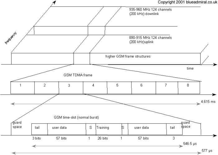
Figure 6 GSM TDMA frame, slots, and bursts
There are three bits at the start and finish of each burst these
are known as the 'tail' and are set to 0 so they can be used to
enhance the receiver performance. The training sequence in the
middle of the burst is used to adapt the parameters of the receiver
to the current path propagation characteristics and to select
the strongest signal in the case of multi-path propagation (check
this). The 'S' flag indicates whether the data field contains
user or network control data.
Two factors allow for the use of simple transmitter hardware:
on the one hand, the slots for uplink and downlink of a physical
TDM channel are separated in frequency (45 MHz for GSM 900 and
95 MHz for GSM 1800 using FDD). On the other hand, the TDMA frames
are shifted in time for three slots. i.e., if the BTS sends
data at time t0 in slot one on the downlink, the MS access slot
one on the uplink at time t0+3.577ms. An MS thus does not need
a full-duplex transmitter, a simpler half-duplex transmitter switching
between receiving and sending is enough. In order to avoid frequency
selective fading, GSM specifies an optional slow frequency hopping
mechanism. MS and BTS may change the carrier frequency after
each frame, based on a common hopping sequence. An MS changes
its frequency between up and downlink slots respectively.